English
- English
- Afrikaans
- Català
- Galego
- беларускі
- lugha ya Kiswahili
- አማርኛ
- ភាសាខ្មែរ
- ქართული
- Hausa
- Кыргыз тили
- Kurdî
- Hmong
- IsiXhosa
- Zulu
- Yoruba
- Тоҷикӣ
- O'zbek
- Igbo
- Sundanese
- Español
- Português
- русский
- Français
- 日本語
- Deutsch
- tiếng Việt
- Italiano
- ภาษาไทย
- Polski
- 한국어
- Malay
- বাংলা ভাষার
- हिन्दी
- Pilipino
- Türkçe
- العربية
- Indonesia
- تمل
- український
- Javanese
- فارسی
- தமிழ்
- नेपाली
- Burmese
- ລາວ
- Қазақша
- Euskal
- Română
- Srpski језик

How to Select, Install, and Maintain Rotary Orbital Hydraulic Motors for Maximum Service Life?
This guide cuts through theory to deliver actionable insights – from sizing the right motor for your application, to proper installation techniques, to daily maintenance practices that maximize service life.
1. Core Operating Principle – What Makes It Deliver High Torque?
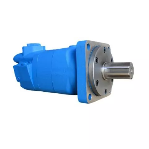
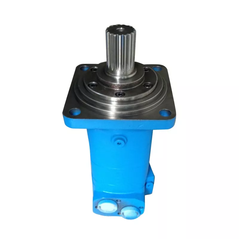
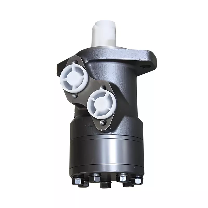
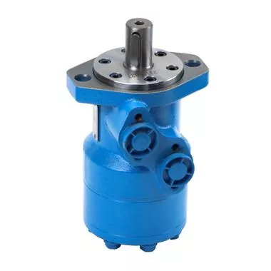
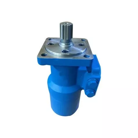
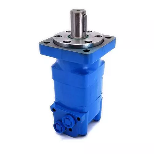
The heart of an orbital motor is an internal meshing gear set – a rotor (outer gear) and a stator (inner gear) – with the critical design rule that the rotor has one fewer tooth than the stator. When pressurized hydraulic fluid enters the motor, it forces the rotor to perform an orbital (planetary) motion inside the stator. This motion is transmitted via an internal coupling shaft to the output shaft, converting the orbital movement into smooth rotary output.
This design delivers the defining advantage: Low-Speed High-Torque (LSHT) . Unlike vane or piston motors, orbital motors can produce strong, stable torque directly at low RPM without requiring a gear reducer. This is invaluable for applications needing precise speed control and high starting torque under heavy loads.
Two primary stator configurations exist:
-
Gerotor (one-piece stator): The stator is a single internal gear ring. Economical and reliable for moderate-duty cycles.
-
Geroler (roller-equipped stator): Rollers or needles are inserted into the stator teeth, converting sliding friction into rolling friction. This yields higher efficiency, better shock-load resistance, and significantly longer wear life – ideal for heavy-duty, high-frequency operations.
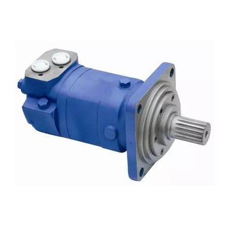
2. Practical Sizing – Choosing the Right "Heart" for Your Machine
An incorrectly sized motor is the #1 cause of premature failure. Undersizing leads to overload damage; oversizing wastes cost and reduces overall system efficiency. Focus on these four critical parameters:
-
Torque, Speed & Displacement (The Triangle) : Displacement (cc/rev) directly determines torque output – larger displacement means more fluid per revolution, hence higher torque, but lower maximum speed. Always define the starting torque (which is typically higher than running torque) and the required operating speed range before selecting displacement. Cross-check with the manufacturer's performance curve – never pick a motor operating at its extreme limits; aim for the peak-efficiency zone of your system's pressure/flow profile.
-
System Pressure & Flow Rate: Confirm your power unit's continuous working pressure and maximum available flow. Pressure limits the peak torque, while flow determines the attainable top speed. Compare these against the motor's rated specifications. Ensure the motor's maximum pressure rating has a reasonable safety margin above your system's peak spikes (use a pressure-relief valve set appropriately).
-
Mounting & Shaft Loading: Beyond bolt patterns and flange sizes, radial load capacity on the output shaft is often overlooked. If you are mounting a sprocket, pulley, or belt drive directly on the shaft, significant side loads are introduced. In such cases, you must select a motor with heavy-duty bearings and consult the manufacturer's radial load rating chart. Ignoring this leads to rapid bearing failure and seal leakage.
-
Environmental & Special Requirements: For extreme ambient temperatures, dusty conditions, or high-humidity environments, specify upgraded seals (e.g., Viton or HNBR) and corrosion-resistant materials. For applications requiring dynamic braking or speed sensing, consider integrated options like brake valves, tachometers, or proportional control valves.
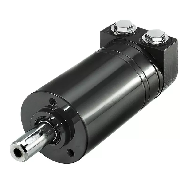
3. Installation & Commissioning – Details That Make or Break Performance
A perfectly selected motor can fail quickly if installed incorrectly. Follow these non-negotiable steps:
- Precise Shaft Alignment: Absolute coaxial alignment between the motor shaft and the driven load is mandatory. Any angular or parallel misalignment introduces radial or axial forces that drastically shorten bearing life. Use a dial indicator or laser alignment tool and adhere strictly to the manufacturer's tolerances (typically ≤ 0.05 mm radial runout).
-
Correct Port Connections: Double-check port identification – Pressure (P), Return (T), and Drain (L) . The drain port is critical: it must be piped separately back to the tank with minimal back pressure (usually < 5–10 bar, consult specs). Never plug the drain port – doing so will blow the shaft seal immediately.
-
System Flushing Before Start-up: Before connecting the motor, flush the entire hydraulic system (hoses, valves, coolers) with clean fluid to remove welding slag, dirt, or debris left from installation. Contaminants introduced during setup are a leading cause of early wear.
-
Initial Break-in Procedure: For new or rebuilt motors, run the unit at 30–50% of rated load for approximately 30–60 minutes before full-load operation. This allows the internal gears and bearings to mate properly and stabilizes internal clearances, significantly extending long-term durability.
4. Daily Maintenance & Rapid Fault Diagnosis
Remember the golden rule: 90% of hydraulic motor failures trace back to fluid contamination or improper fluid temperature. Maintenance is not optional – it is the lifeline of your equipment.
Fluid Management – Your #1 Priority:
-
Cleanliness: Solid particles act as abrasive lapping compound, wearing down the precision-machined rotor-stator pair. This increases internal leakage, drops volumetric efficiency, and reduces torque. Target a cleanliness level of ISO 4406 18/16/13 or better, and inspect/replace return-line filters regularly. Use a differential pressure indicator on the filter housing.
-
Viscosity & Temperature: The optimal viscosity range is 20–43 cSt at 50°C. Maintain oil temperature below 60°C for continuous duty; never exceed 85°C even on peaks. High temperatures thin the oil, reducing lubricity and accelerating seal degradation. Low temperatures increase viscous drag, causing cavitation and sluggish starts. Install a temperature gauge and cooler if necessary.
-
Never Mix Fluid Types: Absolutely DO NOT use engine oil as a substitute for hydraulic fluid. Their additive packages are incompatible. Mixing can cause seal swelling, foaming, varnishing, and catastrophic failure. Always use the OEM-recommended hydraulic fluid grade.
Quick Fault Diagnosis Table
| Symptom | Likely Root Cause(s) | Corrective Action |
|---|---|---|
| Unstable speed / jerking / crawling | 1. Air entrainment in fluid 2. Inconsistent supply flow 3. Excessive internal leakage (worn gears) | 1. Check suction line for leaks & bleed air 2. Inspect pump and relief valve for fluctuations 3. Perform leakage test; rebuild or replace if worn |
| Loss of torque / fails to drive load | 1. System pressure too low 2. Internal bypassing (rotor/stator wear) | 1. Check relief valve setting & pump output 2. Measure case drain flow – high flow indicates wear |
| External oil leakage | 1. Shaft seal aged or damaged 2. Drain line back-pressure too high 3. Loose mounting bolts | 1. Replace seal with correct type 2. Unblock drain line & check for restrictions 3. Re-torque bolts to specification |
| Abnormal noise / vibration | 1. Misalignment or loose coupling 2. Fluid viscosity too high / aeration | 1. Realign shaft & tighten connections 2. Check oil temperature & suction strainer |
Scheduled Health Checks
Incorporate these into your preventive maintenance plan:
-
Weekly: Check external casing temperature (use an infrared thermometer) and listen for unusual knocking or whining.
-
Monthly: Inspect all hose fittings and seals for weeping.
-
Quarterly: Take an oil sample and send it for spectrometric analysis – rising levels of iron, copper, or silicon particles are early warning signs of internal wear long before performance drops visibly.
A rotary orbital hydraulic motor is a robust and reliable workhorse when treated correctly. Success lies in three pillars: sizing it accurately for your real-world load profile, installing it with surgical precision, and maintaining fluid health as a non-negotiable discipline. When in doubt, always refer to the manufacturer's specific performance curves and service intervals – and do not hesitate to involve their application engineers for complex duty cycles or custom integrations.
If you need further elaboration on any specific aspect – such as detailed radial load calculations, integrated valve selection, or high-temperature sealing options – please let me know and I can expand.
Related News
- How Are High-Speed Hydraulic Motors Improving Industrial Equipment Performance?
- How Are Gear Hydraulic Motors Advancing Modern Machinery?
- Oscillating Hydraulic Motors: How Do They Work and Where Are They Used?
- Hydraulic Motor Won't Cooperate? These On-Site Fixes Beat Calling the Dealer
- Small Orbital Hydraulic Motors: How to Choose the Right Compact Power Solution for Your Equipment
- How Do Gear Hydraulic Motors Work?
Leave me a message